
Sheet Metal Fabrication
PartsMake provides cutting, bending, welding, hardware installation, finishing, and assembly support for custom sheet metal parts.
Quotes are reviewed around material and thickness, flat-pattern geometry, formed datums, weld requirements, installed hardware, appearance, and production quantity.
Verified production range: 1–50,000+ pieces
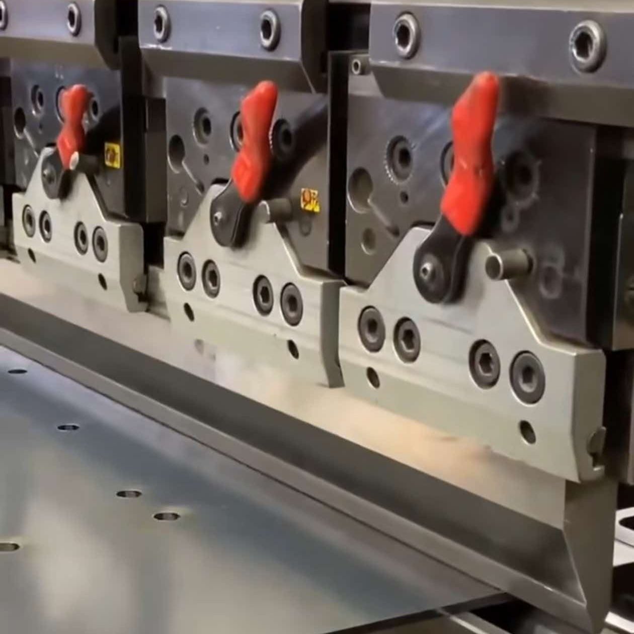
Sheet metal purchasing guide
Define the flat pattern, formed part, and assembly separately
A usable quote needs more than an overall size. Material and thickness drive cutting and bending; bend geometry changes the developed blank; welding changes the finished assembly; and installed hardware adds its own hole, orientation, and clearance requirements.
Maximum sheet size
3000 × 1500 mm
Press-brake capacity
200 ton / 3000 mm
Verified quantity range
1–50,000+ pieces
| Material family | Verified maximum cutting thickness | What to define on the RFQ |
|---|---|---|
| Carbon steel | Up to 25 mm | Grade, thickness, finish condition, coating, and whether the part will be welded or formed. |
| Stainless steel | Up to 20 mm | Exact grade, surface direction, protective film, visible face, and cosmetic acceptance. |
| Aluminum | Up to 20 mm | Alloy and temper, grain direction where relevant, forming severity, finish, and appearance requirements. |
| Copper and brass | Up to 10 mm | Alloy, temper, conductivity or appearance requirement, surface protection, and joining method. |
These are maximum cutting ranges from the current PartsMake company profile—not a promise that every grade, feature, or bend is feasible at the maximum thickness. A universal minimum sheet thickness is not defined in the profile and must be reviewed by material, handling, cutting, forming, and distortion requirements.
DFM starting rules
Hole size, bend clearance, and inside radius
Use the following as quotation-stage screening rules, not guaranteed capabilities. In the formulas below, t is material thickness and R is the inside bend radius.
| Feature | DFM starting point | Why it changes | Drawing guidance |
|---|---|---|---|
| Minimum hole diameter | Start at ≥ 1t for ductile sheet; harder material or punching may require a larger ratio. | Cutting method, hardness, thickness, hole quality, tool strength, and required edge condition. | Dimension the finished hole and identify whether it is cut, punched, drilled, tapped, or reamed. |
| Hole edge to bend line | Begin review around R + 2t; increase clearance for large holes, slots, hard material, or severe bends. | A nearby bend can stretch or pull the opening out of round and change its position. | Show the bend line and dimension the hole from functional datums on the formed part. |
| Inside bend radius | Start near 1t for many ductile sheets; harder, thicker, high-strength, or across-grain bends often need more. | Alloy, temper, grain direction, tooling opening, bend method, angle, and cosmetic limits. | Call out the required inside radius only where functional; otherwise allow the fabricator to match available tooling. |
| Bend relief and corner relief | Extend relief beyond the bend zone and size it to prevent tearing or material overlap. | Thickness, radius, adjacent flange geometry, surface requirement, and weld closure. | Show acceptable relief shape or allow DFM adjustment before release. |
Welding distortion and appearance level
Heat input, joint design, weld length, sequence, fit-up, material, thickness, and fixturing all affect distortion. Identify the functional datums and allowed straightening method instead of applying a tight overall tolerance without a weld plan.
Functional
Strength and assembly matter most; normal weld profile, heat tint, and fabrication marks may be acceptable unless restricted.
Controlled cosmetic
Define visible faces, weld continuity, spatter limits, grinding extent, and finish direction.
Show surface
Provide an approved appearance standard or sample covering weld blending, waviness, scratches, pits, color, and viewing conditions.
These are project-definition levels, not named certification grades. Acceptance criteria should be agreed before production.
PEM hardware and assembly inputs
- Exact hardware: manufacturer, part number, thread, material, finish, and approved equivalent policy.
- Sheet compatibility: grade, hardness, thickness range, and required installation hole.
- Orientation: installation side, head direction, flush requirement, and visible face.
- Clearance: distance from edges, bends, embosses, welds, and other hardware so tooling can access the location.
- Performance: torque, push-out, pull-through, electrical contact, or grounding requirement where applicable.
- Process order: whether hardware is installed before or after coating, plus masking and thread-protection needs.
- Assembly: mating parts, fastener access, fixture datums, sequence, and final inspection method.
Tolerance strategy
Do not apply flat-pattern tolerance to the finished part
Cut profiles, formed dimensions, and welded assemblies are different control stages. The drawing should identify which dimensions are inspection requirements after forming and assembly.
| Control stage | Verified capability / basis | How to specify it |
|---|---|---|
| Flat pattern / cut profile | Typical cutting tolerance ±0.10 mm; selected work down to ±0.05 mm. | Use for cut edges and features before bending. The production flat pattern may differ from the nominal CAD blank after bend allowance review. |
| Formed part | Typical bend dimensional tolerance ±0.25 mm and bend angle ±0.5°. | Dimension functional flange lengths, hole positions, angles, and datums in the formed state. Account for material and bend accumulation. |
| Welded assembly | Project-specific; affected by heat input, joint layout, sequence, fixturing, straightening, and measurement setup. | Define assembly datums, critical interfaces, profile or flatness needs, weld symbols, and appearance acceptance separately. |
The values above are overall capability ranges from the current company profile, not automatic tolerances for every material, thickness, feature, or assembly.
Explore the category
Sheet metal fabrication resources
Review practical manufacturing topics covering cutting, forming, welding, stamping, assembly, and related production considerations.
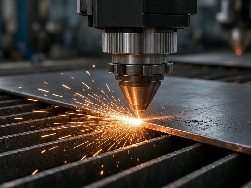
Precision Laser Cutting Services | Custom Sheet Metal Fabrication | PartsMake
PartsMake provides high-precision laser cutting services for custom sheet metal components. Serving OEMs and engineers with strict tolerance control and fast turnaround.
View details →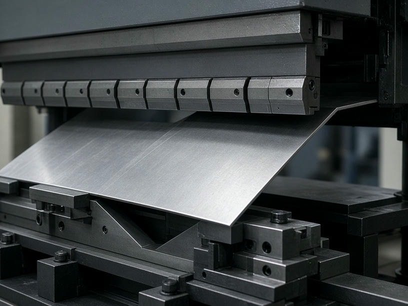
Precision Sheet Metal Bending Services | PartsMake
Custom sheet metal bending services for OEMs and engineers. Precision press brake operations, tight tolerances, and expert DFM support. Request a quote today.
View details →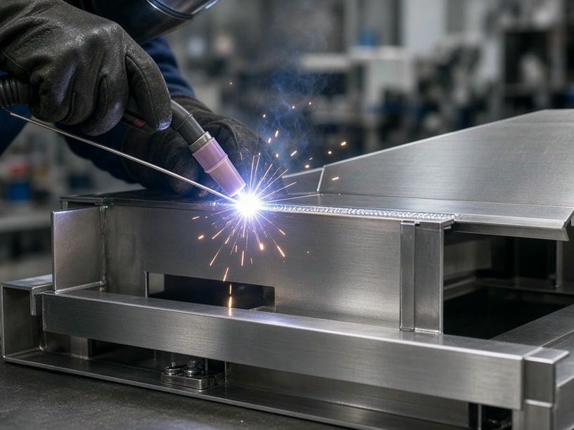
Custom Sheet Metal Welding Services | PartsMake
PartsMake provides precision sheet metal welding, including TIG, MIG, Laser, and Spot welding. From prototypes to production, we manage distortion and tolerances. Get a quote.
View details →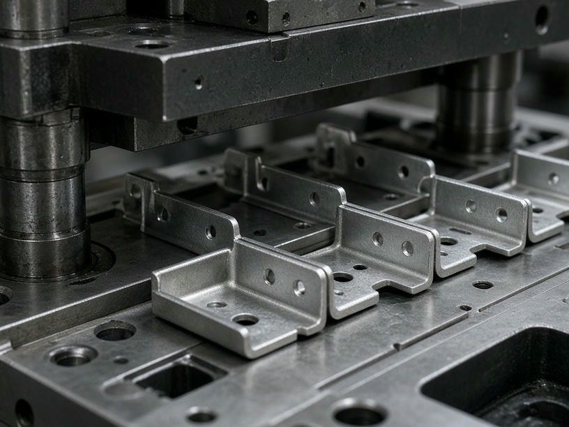
Custom Sheet Metal Stamping Services | High-Volume Metal Parts Manufacturing
Streamline your production with professional sheet metal stamping. We balance tooling costs with unit pricing for high-volume metal components. Get a quote.
View details →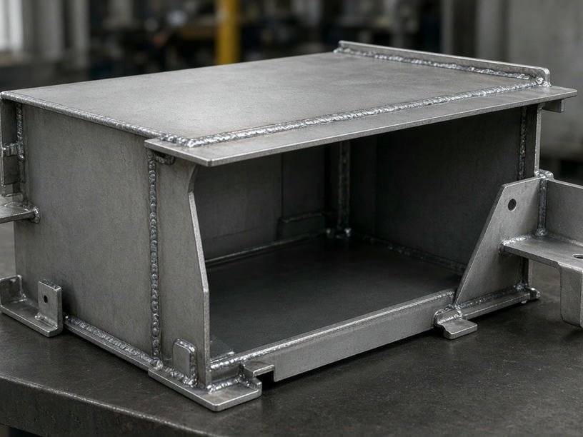
Custom Sheet Metal Assembly Services | Precision Fabrication & Integration
Streamline your production with PartsMake’s end-to-end sheet metal assembly services. From laser cutting and PEM hardware to complete mechanical integration.
View details →Materials
Materials for sheet metal fabrication
We cut, form, and weld a range of sheet metals. Select a material to review its formability, corrosion resistance, and typical applications.
Verified capability data
Sheet metal fabrication capability specifications
Cutting, bending, welding, material thickness, and quantity ranges follow the current PartsMake company profile.
| Parameter | Verified range |
|---|---|
| Laser cutting / sheet size | Fiber laser cutting; maximum sheet size 3000 × 1500 mm |
| Carbon steel thickness | Up to 25 mm |
| Stainless steel / aluminum thickness | Up to 20 mm |
| Copper / brass thickness | Up to 10 mm |
| Typical / precision cutting tolerance | ±0.10 mm / down to ±0.05 mm |
| Minimum hole diameter | Approximately equal to material thickness |
| Press brake / maximum bend length | Up to 200 tons / 3000 mm |
| Typical bending tolerance / angle | ±0.25 mm / ±0.5° |
| Sheet thickness range | Approximately 0.3 mm minimum; typical maximum 20–25 mm |
| Welding | TIG, MIG, spot, and laser welding |
| Hardware installation | PEM nuts, studs, standoffs, and inserts |
| Production quantity | 1–50,000+ pieces |
| Materials | Aluminum, stainless steel, mild steel, galvanized steel, copper, and brass |
Final dimensions depend on material grade and thickness, bend direction, tooling, feature-to-bend spacing, weld sequence, finish build, and inspection datum strategy.
Start your project
Request a sheet metal fabrication quote
Send your CAD files, drawings, material preferences, estimated quantities, tolerances, and finishing requirements. PartsMake will review the project and help identify the right manufacturing path.
- ✓Prototype and production quantities supported
- ✓Cutting, bending, welding, finishing, and assembly coordination
- ✓Engineering and inspection support throughout the project