
Injection Molding
PartsMake supports DFM review, mold development, and molded-part production for prototype, bridge, and production programs.
Tooling decisions are planned around design maturity, resin, critical dimensions, appearance requirements, launch quantity, and lifetime demand.
Verified production range: 100–1,000,000+ pieces
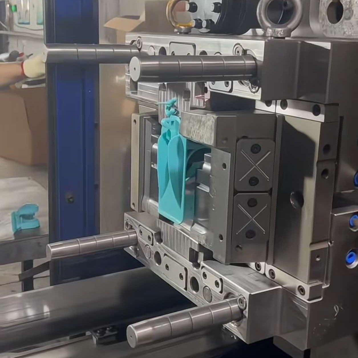
Tooling and production planning
Choose the mold around design maturity and demand
Prototype, bridge, and production molds solve different purchasing problems. The right choice depends on how stable the design is, how many parts you need now and over the program life, what changes remain likely, and how tooling cost should be amortized.
Verified quantity range
100–1,000,000+ pieces
Clamping force
50–800 ton
Verified mold-life range
10,000–1,000,000+ cycles
| Tooling route | Choose it when | What the buyer is optimizing | Economic logic | Main limitation |
|---|---|---|---|---|
| Prototype mold | You need molded-material parts to validate fit, function, assembly, or early market demand while changes are still possible. | Lower initial commitment, learning speed, and controlled design risk. | Useful when avoiding an expensive redesign is more important than reaching the lowest unit price immediately. | Not intended to carry an uncertain design straight into long-term high-volume production without review. |
| Bridge mold | The design is largely stable and saleable parts are needed before full production tooling or demand is fully proven. | Earlier supply, demand validation, and a smoother ramp into production. | Spreads a moderate tooling commitment across launch or ramp quantities while preserving a path to production tooling. | May create duplicate tooling investment if volume, design, and production requirements are already certain. |
| Production mold | The design, resin, quality plan, annual demand, and program life are sufficiently defined. | Repeatability, output, maintenance planning, and lower unit cost over sustained demand. | Higher tooling investment is amortized across a larger confirmed lifetime quantity. | Late design changes, unclear demand, or unresolved molding risk can make early commitment expensive. |
Quantity economics
Evaluate total program cost—not tooling price alone
A useful comparison is tooling cost ÷ expected lifetime quantity + molded-part cost + secondary operations + expected change risk. The verified manufacturing range is 100–1,000,000+ pieces, but there is no universal break-even quantity: part size, resin, cavity strategy, cycle time, mold construction, inspection, finishing, and forecast confidence all affect the result.
Low or uncertain demand
Compare prototype tooling with CNC machining or 3D printing before committing.
Launch and ramp
Bridge tooling can protect schedule while demand and design are confirmed.
Stable repeat demand
Production tooling can justify higher investment through longer-run unit economics.
When injection molding may not be the best choice
- The design is changing weekly: machine or print the next iteration before freezing tooling.
- Demand is too low or uncertain to absorb tooling: compare CNC machining and 3D printing on total required quantity.
- The part exceeds the verified molding window: current profile limits are approximately 800 × 600 × 300 mm and about 5 kg, subject to geometry and resin.
- The geometry cannot release from a mold economically: deep undercuts, inaccessible features, zero-draft surfaces, or enclosed channels may require redesign, actions, or another process.
- The part is better made as formed sheet: thin panels, brackets, and enclosures may fit sheet metal fabrication better.
Key DFM inputs for a useful mold review
- Geometry: 3D CAD plus a controlled 2D drawing.
- Material: resin grade, color, fillers, additives, and approved alternatives.
- Demand: first order, annual usage, lot size, ramp plan, and lifetime quantity.
- CTQ features: datums, critical dimensions, fits, and functional tolerance needs.
- Appearance: texture, gloss, color boundary, gate, ejector, knit-line, and witness-mark restrictions.
- Use conditions: loads, temperature, chemicals, UV, wear, flame, and assembly interfaces.
- Secondary work: inserts, overmolding, printing, painting, welding, or assembly.
- Acceptance: inspection method, sampling, packaging, traceability, and required documentation.
Tolerance planning
Molded tolerance is conditional—not one number for every feature
The verified profile gives a typical range of ±0.05–0.20 mm, with selected features potentially reaching ±0.03 mm. These values are not automatic drawing-wide tolerances. They must be reviewed against the resin, dimension length, feature geometry, mold layout, and measurement method.
| Constraint | What changes the result | Purchasing / drawing implication |
|---|---|---|
| Material | Resin shrinkage, fiber or mineral fill, moisture response, orientation, and post-mold conditioning. | Name the exact grade and condition; do not transfer a tolerance from one resin to another. |
| Dimension size | Long dimensions accumulate shrinkage and thermal variation; local features are controlled differently from overall size. | Identify which dimensions truly drive fit and allow realistic limits on non-critical overall dimensions. |
| Geometry | Wall transitions, ribs, bosses, deep cores, undercuts, draft, gate location, and parting-line relationships affect distortion and repeatability. | Apply tight limits selectively and review datum strategy, tool access, ejection, and warp risk during DFM. |
| Mold relationship | Features formed in the same mold half are generally controlled differently from features spanning slides, inserts, or opposing mold halves. | Mark critical feature relationships so the tooling concept can be designed around them. |
| Measurement | Cooling time, conditioning, fixture, datum alignment, and inspection temperature influence reported results. | Define how and when critical dimensions will be measured before tool approval. |
Recommended nominal wall thickness is 1–3 mm, with approximately 0.5 mm possible only where material and geometry permit. Draft is typically 0.5–2°. Both affect filling, cooling, ejection, appearance, and dimensional stability.
Category overview
Explore injection molding services
Review the molding solutions below to find the right approach for your part geometry, material requirements, production stage, and expected quantities.
01 / Material strategy
Select materials for function and finish
Balance strength, flexibility, temperature resistance, appearance, and production requirements before the mold is built.
02 / Mold development
Turn design intent into reliable tooling
Parting lines, gates, draft, cooling, ejection, and critical features are considered together to support consistent molding.
03 / Quality control
Verify parts throughout production
Inspection and project communication help keep dimensions, appearance, and functional requirements aligned with the approved design.
Molding solutions
Find the right process for your project
Compare focused manufacturing approaches for product development, functional integration, complex geometries, and production readiness.
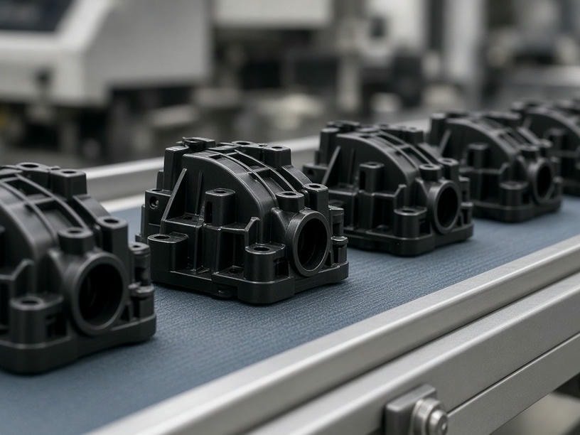
Custom Plastic Injection Molding Services | High-Volume Production | PartsMake
PartsMake provides precision plastic injection molding for engineering prototypes to high-volume production. Expertise in complex polymers and DFM support.
View details →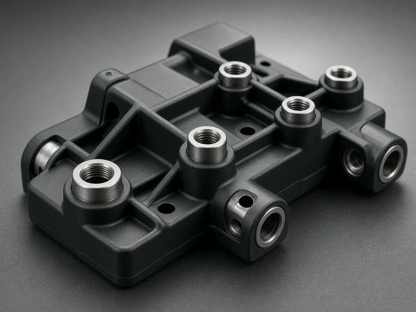
Custom Insert Molding Services | Precision Plastic-Metal Integration | PartsMake
PartsMake provides expert insert molding services for complex plastic-metal assemblies. Precision engineering for brass inserts, terminals, and shafts. Get a quote today.
View details →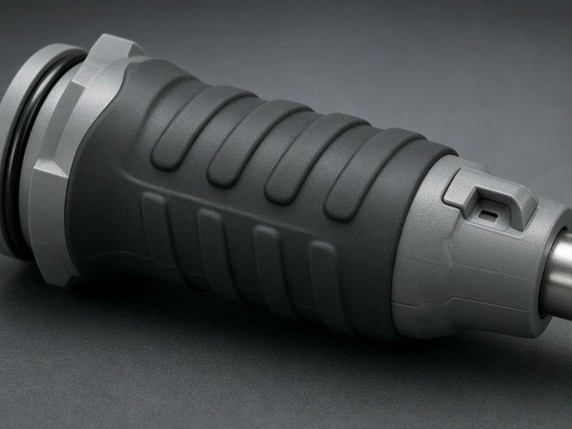
Custom Overmolding Services for Multi-Material Plastic Parts | PartsMake
Expert overmolding services for complex plastic assemblies. We specialize in substrate bonding, TPE/TPU integration, and precision molding for high-volume production.
View details →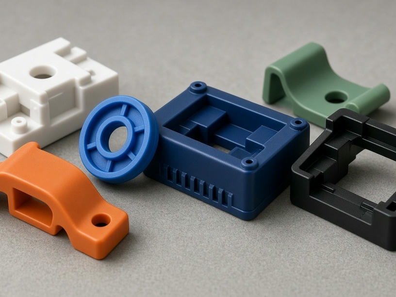
Custom Prototype Molding Services | Rapid Injection Molding | PartsMake
PartsMake provides high-quality prototype molding services. Accelerate product development with rapid tooling, functional resin parts, and DFM analysis. Request a quote today.
View details →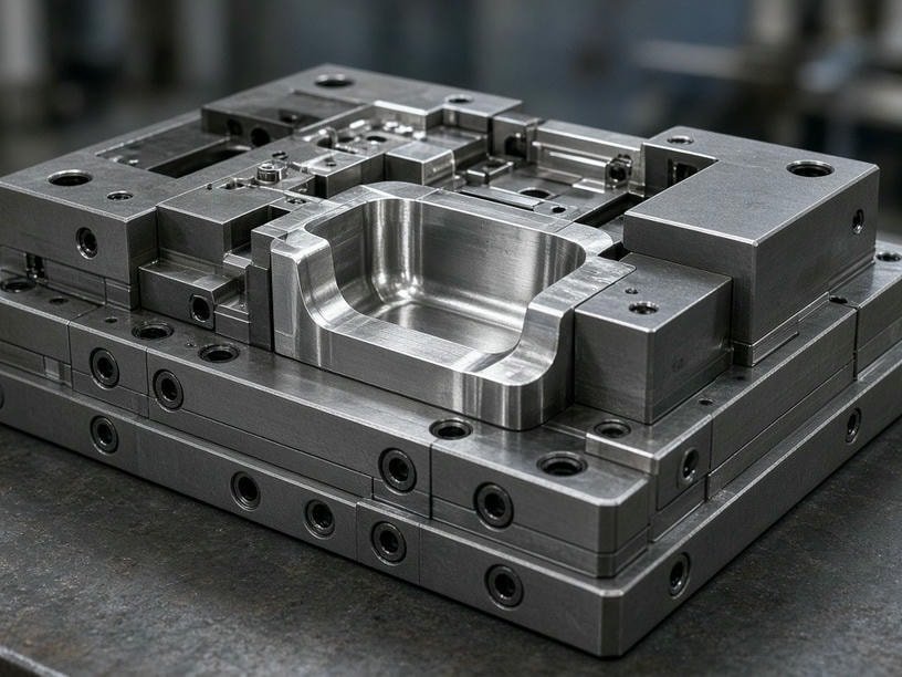
Custom Injection Mold Tooling Services | High-Precision Mold Design | PartsMake
PartsMake delivers professional injection mold tooling services, from DFM and steel selection to high-volume production molds. P20, 718H, S136, H13 steel options.
View details →Materials
Materials for injection molding
We mold a broad range of thermoplastics and engineering resins. Select a material to compare its properties, processing behavior, and typical applications.
Verified capability data
Injection molding capability specifications
Tooling, press, part, tolerance, and quantity ranges follow the current PartsMake company profile.
| Parameter | Verified range |
|---|---|
| Mold types | Prototype, bridge, and production molds |
| Mold cavities | Single-cavity and multi-cavity |
| Mold base / steel | LKM, DME, or equivalent; P20, 718H, NAK80, S136, H13 |
| Maximum mold size | Up to approximately 1000 × 800 mm |
| Injection machine size | 50–800 ton |
| Maximum part size / weight | Approximately 800 × 600 × 300 mm; below 1 g to approximately 5 kg |
| Typical molding tolerance | ±0.05–0.20 mm |
| Precision molding tolerance | Down to ±0.03 mm |
| Minimum / recommended wall thickness | Approximately 0.5 mm / 1.0–3.0 mm |
| Draft angle | Typically 0.5°–2° |
| Surface finish | SPI A1–D3, VDI, and custom textures |
| Insert / overmolding | Supported, including threaded inserts |
| Mold life | 10,000 to 1,000,000+ cycles |
| Production quantity | 100 to 1,000,000+ parts |
| Materials | Standard thermoplastics, engineering polymers, reinforced materials, and high-performance plastics |
Final tolerance and tooling feasibility depend on resin shrinkage, fillers, wall thickness, part size, gate and cooling strategy, draft, geometry, and measurement conditions.
Ready to discuss your molded part?
Share your CAD files, drawings, material preferences, quantities, and target requirements with PartsMake. Our team can help identify the practical path from design review to production.
Get a Quote from PartsMake