
PartsMake Engineering Guide
Types of Milling Operations: Complete Guide to Machining Techniques
Milling can create flat faces, pockets, slots, angled surfaces, threads, and complex profiles. We explain the main types of milling operations, the cutters used for each, and practical factors to consider when choosing a method for a machined part.
In this guide: We classify milling by the geometry being machined and by the mechanism or control approach, then connect those categories to common cutters and project decisions.
What Is Milling and How Does the Process Work?
Milling is a machining process in which a rotating, multi-edge cutter removes material from a workpiece. The cutter and workpiece move relative to one another, and each cutting edge removes a small amount of material as it passes through the cut. Repeated passes produce the required faces, steps, pockets, slots, or contours.
Unlike drilling, which primarily creates a hole along the tool axis, milling can cut in several directions and generate features across a part’s surface. The exact result depends on the cutter geometry, toolpath, workholding, cutting conditions, and the material being machined.
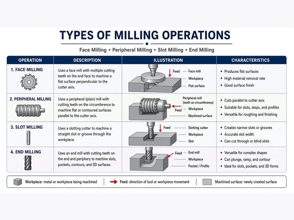
The main elements of a milling setup
-
1
Spindle and cutter
The spindle rotates the cutting tool. Cutter type and diameter determine which surfaces or features can be reached efficiently.
-
2
Workholding and workpiece
A vise, fixture, or other suitable setup locates and supports the material while the cutting forces act on it.
-
3
Axes and feed motion
Machine axes control the relationship between tool and part. A programmed or manual feed determines how the cutter travels through the material.
-
4
Control and inspection
The operator or CNC program directs the operation; measurement checks whether the resulting dimensions and finish meet the drawing requirements.
How Many Types of Milling Operations Exist?
There is no single universal count. Milling operations are commonly grouped in two complementary ways: by the geometry or feature being produced, and by the mechanism or control approach used to make the cut. A single part may combine several operations from both groups.
| Classification | What it describes | Examples |
|---|---|---|
| Workpiece geometry | The feature or surface being cut | Face, slab, slot, side, angle, form, gear |
| Mechanism and control | How the machine is operated or how the cutter engages the material | Manual, CNC, conventional, climb |
For practical planning, we start with the required geometry, then decide which machine, cutter, toolpath, and cutting direction can produce it reliably. This avoids treating familiar labels as mutually exclusive categories.
Types of Milling Operations by Workpiece Geometry
Geometry-based names describe the surface or feature being machined. The operation may be performed on a manual or CNC machine, and the same cutter family may support more than one type of cut.
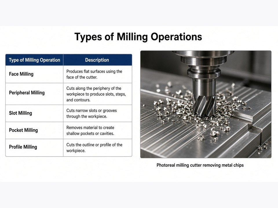
Face Milling
In face milling, the cutter axis is generally perpendicular to the surface being machined, and the cutter’s face performs much of the material removal. The tool travels across the workpiece to create a flat face or bring a surface to size.
Face milling is common for plate surfaces, mounting faces, and broad shoulders. Cutter choice, insert condition, toolpath overlap, machine rigidity, and material all influence the resulting finish.
Plain (Slab) Milling
Plain or slab milling uses a cutter mounted on a horizontal spindle, with the cutter axis parallel to the surface being cut. The cutting edges around the tool’s circumference machine a flat surface as the work moves past it.
It is useful for longer flat surfaces and can remove material efficiently when the setup supports a wide, continuous cut. The cutter width, work support, and available machine configuration affect the practical cutting strategy.
End Milling and Slot Milling
An end mill cuts with its end and peripheral edges, making it versatile for pockets, steps, profiles, and vertical walls. Slot milling creates a channel or groove, often with a tool selected to match the slot width and depth.
For a deep pocket or narrow slot, chip evacuation and tool reach matter. A programmer may use multiple passes rather than remove the full depth at once, depending on tool engagement and part rigidity.
Side, Straddle, and Gang Milling
Side milling cuts a vertical face or side using the cutter’s peripheral teeth. Straddle milling uses cutters positioned on both sides of a workpiece to machine two parallel faces in the same setup.
Gang milling mounts multiple cutters to machine more than one feature in a pass. These approaches can be useful in suitable production setups, but require careful coordination of tool positions, workholding, and cutting load.
Angle, Form, and Gear Milling
Angle milling produces a surface at a defined angle, using an angled cutter or a suitable workpiece orientation. Form milling uses a cutter profile shaped to generate a matching contour, such as a radius or groove.
Gear milling uses a gear-shaped cutter and an indexing or coordinated motion strategy to create tooth spaces. For any specialized profile, the drawing, required geometry, and production approach determine whether milling is suitable.
Thread, Saw, and CAM Milling
Thread milling uses a rotating thread mill and a coordinated toolpath to cut internal or external threads. Compared with a tap, it can offer a different approach to thread production, particularly when the part geometry or machining plan favors interpolation.
A milling saw makes narrow cuts or separates features where the setup permits. CAM milling refers to computer-aided manufacturing software generating and controlling toolpaths; it is a programming method, not a separate cutter geometry. CAM can also guide the machining of a cam profile.
Types of Milling Operations by Mechanism and Control
Some milling terms describe how the machine is controlled; others describe the direction of cutter engagement. Keeping these categories separate helps make a process plan easier to understand.
Manual vs CNC Milling
On a manual milling machine, an operator controls axis movement and cutting actions directly. CNC milling uses a programmed sequence of machine movements to control tool position and operation. Both approaches can remove material; they differ in how motion is directed and repeated.
| Consideration | Manual milling | CNC milling |
|---|---|---|
| Motion control | Operator-guided machine movement | Programmed machine movement |
| Repeatability | Depends strongly on setup and operator execution | A validated program can repeat the intended toolpath |
| Complex geometry | Best suited to operations the machine and operator can control practically | Can coordinate multiple axes for more involved features |
CNC is widely used where a programmed toolpath, repeatable features, or coordinated axes are useful. At PartsMake, we review the CAD model and drawing along with material, tolerances, surface requirements, and quantity before selecting a machining approach.
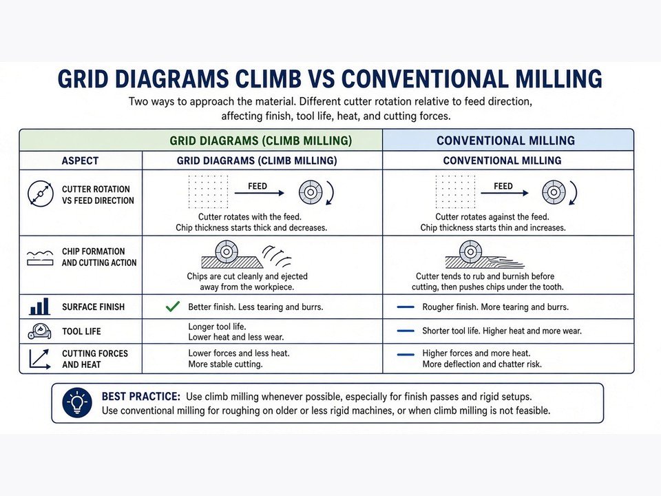
Conventional Milling vs Climb Milling
These terms describe the relationship between cutter rotation and feed direction at the point of engagement. In conventional milling, the cutter moves against the feed direction at the cut; chip thickness starts near zero and increases toward the exit. In climb milling, cutter motion follows the feed direction; the chip starts thicker and becomes thinner as the edge exits.
What the difference means in practice
Surface and tool engagement: Climb milling often produces a favorable cutting action and surface finish when the machine, setup, and cutting conditions support it.
Machine condition: Conventional milling may be preferred on some machines or setups where backlash or movement under cutting load is a concern.
Decision: We consider the machine, material, workholding, cutter, and operation rather than assuming one direction is always correct.
Types of Milling Cutters and Tools
Cutter labels can overlap: for example, an end mill may be chosen for slotting, profiling, or pocketing. The right tool depends on the feature, material, available access, required finish, and how the tool will be supported.
| Cutter type | Typical operation | Practical note |
|---|---|---|
| 1. Face mill | Facing broad flat surfaces | Selected for the face size and machine setup. |
| 2. End mill | Pocketing, profiling, shoulders, and general milling | Available in different diameters, lengths, and end geometries. |
| 3. Slab mill | Plain milling of flat surfaces | Used with a horizontal milling arrangement. |
| 4. Side milling cutter | Machining side faces and grooves | Peripheral teeth cut along the side of the tool. |
| 5. Slot drill | Slots and plunging into material | Tool design and flute geometry affect how it enters the cut. |
| 6. T-slot cutter | Undercut T-shaped slots | A pilot slot is typically made before opening the cross section. |
| 7. Dovetail cutter | Angled dovetail grooves and profiles | The included angle must match the feature design. |
| 8. Angle cutter | Chamfers, V-grooves, and angled surfaces | Choose a tool geometry suited to the required angle. |
| 9. Form cutter | Concave, convex, or other shaped contours | The cutting profile corresponds to the intended contour. |
| 10. Gear cutter | Cutting gear tooth spaces | Requires the appropriate gear geometry and indexing strategy. |
| 11. Thread mill | Internal or external threads | The programmed path must match the thread geometry. |
| 12. Milling saw | Narrow slots and cutoff work | The thin tool needs suitable support and clearance. |
| 13. Fly cutter | Facing a broad surface with a single cutting point | Often used where a sweeping cut is suitable for the setup. |
This list covers 13 common cutter types, but it is not a complete catalog of every tool configuration. Inserts, coatings, flute forms, and tool materials also vary, so the cutter should be specified in context rather than selected from its name alone.
How to Choose the Right Milling Operation
Start with the part requirements, not with a preferred cutter. We review the drawing or CAD model and work through the constraints that determine whether a milling approach can meet the functional and production requirements.
-
1
Identify the material
Material affects tool selection, cutting conditions, chip behavior, and how heat and cutting forces are managed. Share the exact material requirement when submitting a part for review.
-
2
Define geometry and access
Separate the part into faces, pockets, slots, holes, angled surfaces, and profiles. Check whether a cutter can reach each feature without interference and whether a different orientation or setup is needed.
-
3
Prioritize tolerances and finish
Mark critical dimensions, mating faces, and cosmetic surfaces on the drawing. A finish requirement or tight feature relationship may affect the toolpath, machining sequence, or need for a secondary operation.
-
4
Assess machine and workholding needs
Axis access, tool reach, part rigidity, and the number of setups influence how the operation is planned. Complex multi-face parts may benefit from an appropriate multi-axis machining strategy.
-
5
Match the process to quantity and inspection
Prototype, pilot, and repeat production needs can influence setup and process planning. Identify the dimensions that require verification so inspection can be considered from the start.
Frequently Asked Questions
What are the types of milling operations?
Common types include face, plain or slab, end, slot, side, straddle, gang, angle, form, gear, thread, and saw milling. CAM-guided milling describes how toolpaths are programmed and controlled rather than a separate cutter-based operation.
How many types of milling are there?
There is no fixed count because operations can be classified by the geometry they produce or by how cutting and machine control are performed. This guide covers the most common geometry-based operations and the manual, CNC, conventional, and climb distinctions.
What are the 13 different types of milling cutters?
Thirteen common examples are face mills, end mills, slab mills, side milling cutters, slot drills, T-slot cutters, dovetail cutters, angle cutters, form cutters, gear cutters, thread mills, milling saws, and fly cutters. Their suitability depends on the feature, material, access, and machining setup.
What are different types of machining operations?
Machining includes material-removal processes such as milling, turning, drilling, boring, reaming, grinding, and electrical discharge machining (EDM). The right process depends on part geometry, material, tolerances, surface needs, and production requirements.
Plan your next machined part
Choose a milling approach with the part requirements in view.
If you are evaluating a prototype or production component, share the drawing or CAD model along with material, tolerance, finish, and quantity requirements. Our engineering team can review the part and discuss suitable manufacturing considerations.
Contact PartsMakeDiscuss your machining project
Contact PartsMake to discuss your component, manufacturing requirements, or the next step from prototype to production.