
PartsMake Engineering Guide
CNC Prototype Machining: A Complete Guide to Rapid Development
Learn how CNC prototype machining can accelerate product development, from material selection and design for manufacturability to functional testing and cost control. We explain how to move from CAD files to accurate, usable parts—and how to plan a smoother path from prototype to production.
Introduction
CNC prototype machining is the use of computer-controlled cutting processes to make early physical versions of a part directly from a digital design. A machine removes material from a solid workpiece—such as aluminum, steel, brass, or engineering plastic—until the component matches the programmed geometry. The result can be a one-off engineering sample, a small set for fit checks, or a functional part for evaluation.
Product development has moved far beyond hand-shaped mockups and long, tooling-first timelines. CAD and CAM workflows let engineering teams review a design digitally, machine a real part, learn from assembly or testing, and revise the next version. CNC machining is valuable in that loop because it turns a CAD model into a component made from a chosen engineering material, with real interfaces and features to inspect.
Engineering takeaway
A useful prototype does more than resemble the final part: it helps answer a specific question about fit, function, material behavior, assembly, or manufacturability.
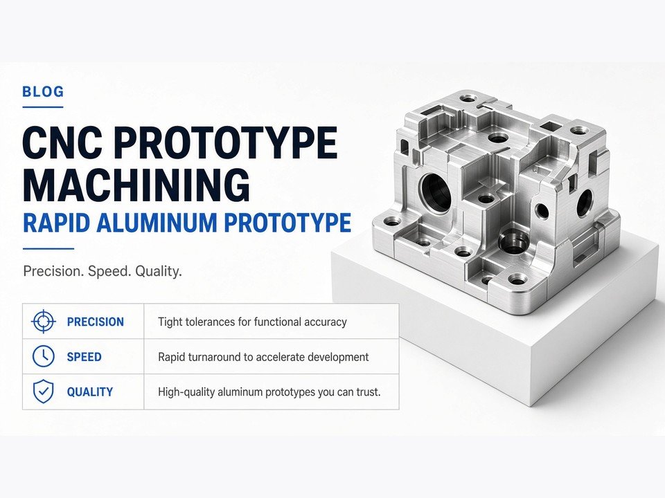
Why Choose CNC Machining for Prototyping?
The right prototype process depends on what the team needs to learn. CNC is particularly useful when dimensional interfaces, a production-relevant material, or mechanical performance matter more than creating a highly intricate shape in a single build.
Precision and Accuracy
CNC processes can produce accurate interfaces and controlled dimensions when the part, setup, tooling, and inspection plan are suitable. This can be important for mating faces, bearing seats, threaded features, and holes that must align during assembly. The achievable result still depends on geometry, material, process selection, and specified tolerances.
Material Versatility
A prototype can be machined from the same material family—or sometimes the same material—as the intended part. Aluminum, steel, brass, and engineering plastics each bring different weight, strength, wear, thermal, and machining considerations, so material choice should follow the test objective.
Functional Testing
A machined component can support practical checks involving loading, heat exposure, fastening, and assembly—provided the selected material and design are appropriate for those tests. Compared with many additive prototypes, this can give engineers a more relevant view of how a solid-stock part behaves in its intended environment.
Seamless Transition
CNC machining can act as a bridge to production: the prototype and later parts may use a related machining approach, avoiding a process change simply to make the first functional samples. The production plan may still evolve as quantity, cost targets, and design maturity become clearer.
When this matters
If your next design review needs a part that bolts into an assembly or accepts a real load, tell your manufacturing partner what the prototype must prove—not only its outside dimensions.
CNC Prototype Machining vs. 3D Printing
Neither process is the universal choice. CNC machining is subtractive and works well for many precise, functional components; 3D printing is additive and can make complex forms without conventional cutting-tool access. Teams often use both at different points in development.
| Decision factor | CNC machining | 3D printing |
|---|---|---|
| Working principle | Removes material from solid stock using programmed cutting tools. | Builds a part by adding material in successive layers or passes. |
| Material support | Can use a range of engineering metals and plastics in stock form. | Uses materials supported by the selected additive process; properties vary by material and build method. |
| Geometry | Tool access and workholding influence which internal and external features are practical. | Can be advantageous for intricate shapes, internal passages, and forms that are difficult to cut. |
| Typical decision | Consider for structural parts, accurate interfaces, and material-relevant functional tests. | Consider for fast form checks, highly complex geometry, or designs that benefit from additive freedom. |
| Cost and timing | Setup, material removal, and finishing affect cost; simple parts can be efficient, while complex machining can add time. | Build complexity and material affect cost and timing; geometry may be economical when machining would need extensive operations. |
Working Principle
A CNC machine follows programmed toolpaths to cut a part from a blank, bar, or other workpiece. 3D printing builds the form from material instead. That fundamental difference affects how each process handles internal features, support, waste, finishing, and material behavior.
Material Support
When a test depends on a particular metal or engineering plastic, CNC may make it possible to evaluate a prototype in a relevant stock material. Additive processes also offer engineering materials, but their properties can be influenced by process and build orientation. Confirm that the selected route matches the test you intend to run.
Geometric Complexity
A freeform enclosure, lattice, or enclosed internal channel may be better suited to additive manufacturing. A bracket with machined mounting faces, a shaft, or a block with accessible pockets may be a strong CNC candidate. For complex components, 5-axis machining, EDM, or a combination of processes may also be worth reviewing.
Cost and Lead Time
For a simple part, CNC setup can be offset by a direct machining route and little post-processing. For a highly intricate, low-volume shape, additive manufacturing may avoid extensive toolpaths or fixtures. Compare the complete job—including material, setup, finishing, inspection, quantity, and delivery need—rather than judging by process name alone.
Key Considerations for CNC Prototype Design (DFM)
Design for manufacturability (DFM) is the practice of shaping a part so it can be produced reliably and efficiently without compromising its required function. A short design review before machining can identify features that need special tools, extra setups, or unusually careful inspection.
Design for Manufacturability
Review the part’s machining orientation, workholding, tool access, and required setups. Consolidating accessible features into fewer orientations can reduce handling and setup effort. Keep tight tolerances only on dimensions that control fit or performance, and identify those critical dimensions clearly.
Wall Thickness and Cavity Depth
Thin walls and deep, narrow cavities can flex or vibrate under cutting forces, making them harder to machine consistently. Long-reach tools may deflect or be more vulnerable to breakage. Where function allows, use more robust wall sections, avoid unnecessarily deep pockets, and ask the machine shop to review difficult features.
Corner Radii
A rotating cutting tool naturally leaves a radius in an internal corner. A perfectly sharp inside corner may require additional operations, a smaller tool, or a different process. Add an internal radius that suits the function and is practical for tooling; consistent radii can also simplify machining.
Standardization
Standard hole sizes, thread forms, fasteners, and material stock sizes are easier to source and plan around. Use a nonstandard feature only when it serves a real design need. On drawings, state thread requirements and depth clearly, and distinguish tapped holes from clearance holes.
Before releasing the model
Ask whether every tight tolerance, deep feature, and sharp internal corner is necessary for the prototype’s test objective. A clear answer helps your machinist protect the important function while pointing out opportunities to simplify the build.
The CNC Prototype Machining Process
A dependable prototype workflow connects engineering intent to machining, finishing, and inspection. At PartsMake, we begin by understanding the part and its application, then review the files and requirements before production begins.
-
1
CAD Design and File Preparation
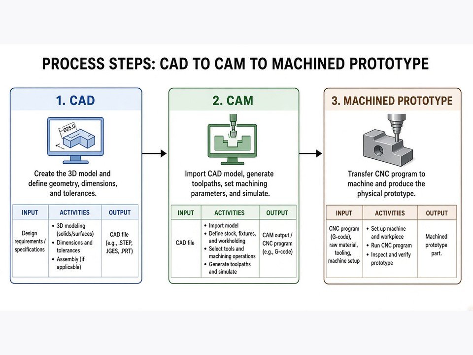
Prepare a solid model and the technical drawing, where available. The model communicates the part’s geometry; the drawing can specify tolerances, datums, threads, surface requirements, and other details that a 3D model may not fully define. Check that units, revision, and model version agree before submitting files.
-
2
Material Selection
Choose a material based on what the prototype must withstand and what the test must demonstrate. Aluminum can be useful when low mass and machinability are priorities; steel may suit applications where strength or wear resistance matters; brass may be appropriate for certain machined components; engineering plastics may suit electrical, chemical, or weight-related needs. The exact grade and application should be confirmed together.
-
3
Programming and Setup
CAM software is used to plan toolpaths from the part geometry. A programmer and machinist consider cutting tools, workholding, machining sequence, and required orientations. For parts with multiple faces or complex surfaces, the team may review whether multi-axis machining or another suitable process can reduce handling or reach the required features.
-
4
Machining and Surface Finishing
The programmed operations create the part, after which edges may be deburred and specified finishing steps applied. Separate functional surfaces from cosmetic expectations: a mating face, sealing area, and visible outer surface may each need different treatment. State finish requirements on the drawing or in the project instructions.
-
5
Inspection and Quality Assurance
Inspection compares the finished part with the requirements. Identify critical dimensions, datums, material expectations, and any surfaces that affect assembly or function. PartsMake can coordinate dimensional and material verification according to drawing and project requirements, with inspection focused on the features that matter to the application.
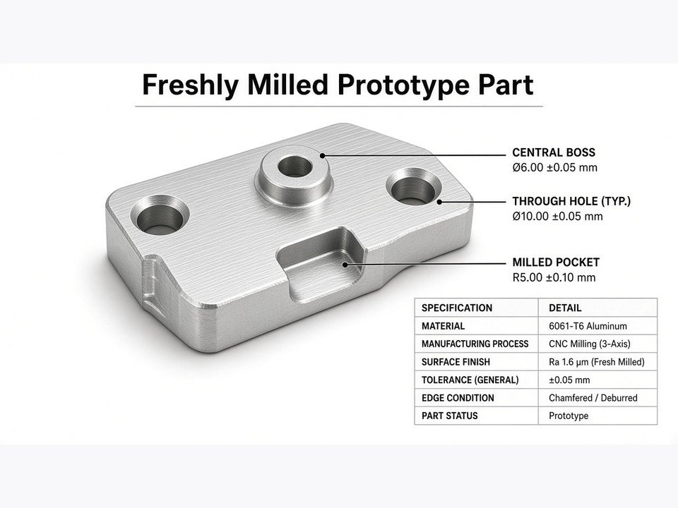
Industries Benefiting from Rapid CNC Prototyping
Across industries, the common benefit is the ability to evaluate real components earlier—before a design is locked into a production route. The most useful prototype is designed around the risks the engineering team needs to resolve.
Automotive and Aerospace
Machined prototypes can help teams assess fit, weight, packaging, and mechanical performance in components such as brackets, housings, and structural details. Material selection and inspection requirements should reflect the part’s intended test and application; prototype parts should not be assumed to meet production or flight requirements without appropriate validation.
Medical Devices
For medical and laboratory equipment, CNC can support development of precise housings, fixtures, and functional components. If a prototype will contact a person, fluid, or a controlled environment, specify the required material and handling expectations. Biocompatibility and regulatory suitability depend on the exact material, process, and intended use and must be verified for the application.
Consumer Electronics
Machined enclosures and internal components can help teams check connector alignment, assembly access, clearances, and thermal or structural design assumptions. CNC prototypes are especially informative when the review depends on a real material or accurate mating features rather than appearance alone.
Industrial Robotics
Robotic and automation systems use parts such as mounts, shafts, grippers, plates, and custom mechanical interfaces. A machined sample can be assembled into a mechanism to check alignment, movement, load paths, and the practicality of service or adjustment before repeat manufacturing.
How to Optimize Cost and Lead Time
A prototype quote reflects more than the time the machine cuts material. Engineering review, material availability, setups, machining complexity, finishing, inspection, and requested delivery timing can all affect the plan. These steps help reduce avoidable effort without weakening the design intent.
Batching Parts
If several parts share a material or can be produced in a coordinated run, ask whether they can be batched. Combining parts may reduce repeated setup effort, though the benefit depends on part geometry, workholding, inspection, and schedule. Provide the full part list and quantities so the shop can evaluate the group as a job.
Material Choice
A commonly available, machinable alloy may be a practical choice when it meets the test requirement. Avoid specifying a premium or unusual material by default if the prototype’s purpose can be met with a more accessible option. If the prototype must represent a production material, say so early so the selection supports a meaningful evaluation.
Clear Communication
Send the current CAD model, a drawing with units and tolerances, material requirements, surface expectations, quantity, and delivery target. Flag critical features and explain where the part will be used. When a requirement is uncertain, ask for a manufacturing review rather than leaving the supplier to infer intent.
At PartsMake, our engineering team reviews geometry, materials, tolerances, critical dimensions, finishes, quantity, and intended application before production. That early discussion helps surface manufacturing risks and clarify what needs to be controlled on the finished part.
Frequently Asked Questions
How much does CNC prototyping cost?
There is no single price for a CNC prototype. Cost depends on the selected material, part geometry, number of setups, machining time, tolerance and inspection requirements, finishing, quantity, and schedule urgency. A complete model and drawing—plus clear notes about the part’s purpose—help a manufacturing partner assess the job and identify possible cost reductions.
Is CNC a hard job?
CNC machining combines technical programming with hands-on manufacturing judgment. A CNC programmer plans toolpaths and operations, while a machinist sets up and monitors the work, manages tools and workholding, and helps ensure the part matches requirements. Complex prototypes call for careful communication between design and manufacturing.
Will CNC be replaced by AI?
AI and automation can assist with tasks such as reviewing designs for manufacturability, supporting programming workflows, and improving process planning. They do not remove the need to make, fixture, cut, finish, and inspect a physical part. Experienced engineering and machining judgment remains important, especially when a prototype has unusual features or critical requirements.
What is a prototype machinist?
A prototype machinist makes low-volume, often one-off parts from engineering designs. The role requires machining knowledge and the ability to interpret drawings, select practical setups and tooling, adapt to design changes, and work with the engineering team to meet the part’s functional and dimensional requirements.
Conclusion
CNC prototype machining helps turn a digital design into a physical component that can be assembled, measured, and evaluated. Its value is strongest when the prototype needs relevant material properties, accurate interfaces, or a credible mechanical test. Good DFM, intentional material selection, clear drawings, and an inspection plan help make each iteration more informative and can reduce avoidable time and cost.
Before choosing a manufacturing route, define what you need the next prototype to prove and consider its geometry, material, quantity, tolerances, finish, and delivery needs. The right manufacturing partner should review those details, explain process trade-offs, and support the project from early samples toward pilot and repeat production. PartsMake works with customers on custom metal and plastic components across CNC machining and related manufacturing processes, with engineering review before production begins.
Plan your next prototype
Discuss your CNC prototype machining requirements with PartsMake
Share your CAD files, drawings, material preferences, quantity, critical dimensions, and intended application. We can review the manufacturing approach and help you plan the next step from prototype toward production.